
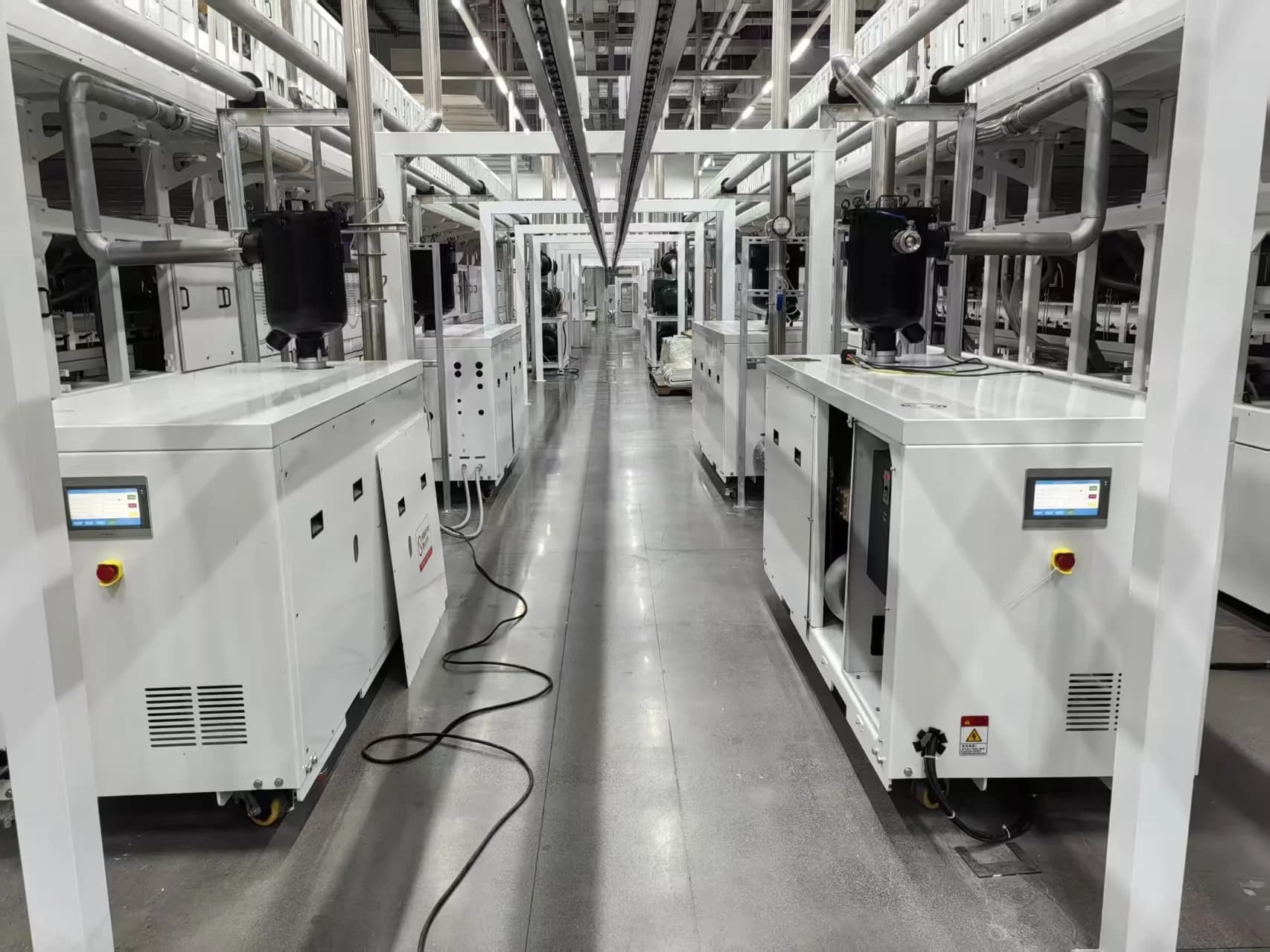
- Send pressure and required volumetric flow rate first. Those two values are enough to open the RFQ.
- If liquid carryover is present or suspected, tell us what the liquid is and when it reaches the vacuum line. Corrosion, solids, crystallization, or solidification can change the protection around the pump.
- A dry screw vacuum pump package can be reviewed for wet carryover into the working chamber. The protection around the pump still has to match the liquid and solids risk.
- If liquid can remain in the package after shutdown, we need to look beyond the pump head. The review may include separation, drainage, inlet filtration, purge, and the startup logic used before the next run.
- Sticky or crystallizing media need special attention after the system cools down. Residue in the wrong place can raise starting current or make the pump difficult to restart.
Why liquid carryover changes the pump review
Once liquid reaches the vacuum line, the selection question changes. The pump still has to meet the pressure and required volumetric flow rate, but the package also has to deal with what the liquid may touch, where it can collect, and what happens before the next startup.
The first RFQ can stay simple. Send the pressure or pressure range and the required volumetric flow rate first; SC Air Power Tech can use those values to check the operating point before asking for wet carryover details.
From there, the liquid decides the next layer of the review. Water, non-corrosive process liquid, solvent, corrosive liquid, slurry, sticky residue, and crystallizing media can point to different material, sealing, separation, drainage, purge, or inlet-protection decisions.
When liquid enters the pump chamber during operation, we also need to ask what remains there after shutdown. If the chamber is not drained or cleared before the next run, sticky, crystallized, or solidified residue can raise starting current or make the pump difficult to start.
Common sources of liquid carryover
Wet carryover is usually created by the process condition. Liquid may be pulled from the vessel with the gas stream, or vapor may cool and condense somewhere in the line, separator, pump package, or after shutdown.
| Source of liquid carryover | What to check |
|---|---|
| Process liquid entrainment | Whether liquid is pulled from the vessel, filter, tank, or process chamber during normal operation |
| Condensable vapor turning into liquid | Whether vapor cools in the line, separator, pump package, or after shutdown |
| Foam or splashing | Whether liquid reaches the vacuum line during batch changes, loading, or unstable process stages |
| Wet solids or slurry droplets | Whether solid particles may travel with the liquid toward the pump inlet |
| Residue left after operation | Whether liquid, condensate, crystals, or solidified media can remain in the chamber before restart |
For the RFQ, describe when the carryover happens as clearly as the liquid itself. A pump that sees liquid throughout production is reviewed differently from a pump that mainly has residual liquid left in the chamber after the process stops.
What liquid details should be checked
For a wet carryover duty, the pump question starts with the liquid itself: what it is, how much may reach the pump, and whether the package already has a way to separate, drain, or block it.
These details usually change the configuration discussion:
| Detail to confirm | Why it matters |
|---|---|
| Liquid type | Water, solvent, non-corrosive process liquid, corrosive liquid, slurry, and sticky liquid are reviewed differently |
| Corrosion risk | Corrosive liquid may change the material, coating, sealing, and discharge path |
| Solid particles | Solids should be kept away from the rotor chamber and screw pair as much as possible |
| Sticky behavior | Sticky residue can affect drainage, cleaning, shutdown, and restart |
| Crystallizing or solidifying behavior | Media that hardens after cooling can create restart risk |
| Carryover pattern | Continuous carryover, occasional carryover, and residue left after operation need different protection logic |
| Existing separator or drain layout | Existing equipment helps only after its position, capacity, drainage, and maintenance access are checked |
If the liquid is corrosive, the pump model is only a rough starting point. SC needs to check how aggressive the liquid is, where it may contact the system, and whether condensate changes the material or coating decision.
If the liquid can crystallize or become solid after shutdown, the operating program becomes part of the pump package. Purge, shutdown sequence, warm-up logic, or a customized restart procedure may be reviewed to reduce abnormal starting current or difficult startup.
Why separator, drainage, and inlet protection matter
With wet carryover, the pump head is reviewed together with the inlet side of the system. Before confirming the package, we need to know where liquid can be separated, where it can collect, and how it leaves the system.
A gas-liquid separator is usually discussed before the pump inlet. Its layout depends on liquid volume, gas velocity, available space, drainage method, and how the operator will clean or inspect it.
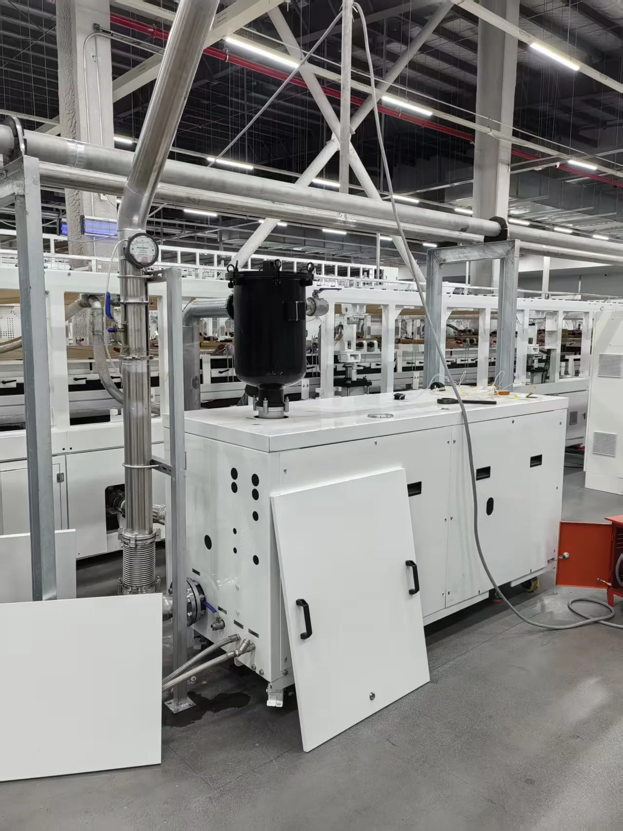
Collection is only useful when the liquid can be removed at the right time. If the drain point is too small, difficult to access, or placed in the wrong part of the line, liquid may still remain in the package after operation.
If solids may travel with the liquid, separation alone is not enough. Inlet filtration or another protection method may be needed to keep particles away from the rotor chamber and screw pair.
The package review changes with the medium. Water or non-corrosive liquid is one discussion; corrosive condensate, sticky solvent residue, crystallizing media, or droplets carrying solids can require a different protection plan.
Crystallizing medium example from a photovoltaic project
One photovoltaic project shipped to Qinhuangdao, Hebei, China used a QER950 dry screw vacuum pump on a process stream that contained EVA adhesive. Under the customer's operating condition, the EVA could stay in the gas phase while the system was running, then return to a glue-like state after cooling.
The chamber had to be evacuated from atmospheric pressure to below 100 Pa(a) within a short time, then stabilize around a working vacuum of 50 Pa(a).
In the actual test, the pump reached a maximum volumetric flow rate of 1050 m3/h while pulling the chamber down from atmospheric pressure toward 100 Pa(a). Near the target vacuum range, the tested point was 45 Pa(a), where the pump maintained 892 m3/h.
The difficult part came after shutdown. In our first cooperation with this company, we did not pay enough attention to what the EVA would do inside the pump head after the chamber cooled. The pump head later had to return to the factory, and the cleaning work required full disassembly of the chamber.
After that, the shutdown procedure was changed. Before stopping the machine after use, a large volume of nitrogen was introduced to purge the chamber and remove the EVA medium before it could remain on the rotor-chamber surfaces and affect the next startup.
This is why sticky or crystallizing media should be discussed before the package is finalized. The pressure and required volumetric flow rate start the RFQ, but shutdown behavior, purge logic, and material behavior after cooling can decide whether the next startup is affected.
What to send in the first message
For the first RFQ, pressure or pressure range and required volumetric flow rate are enough to open the discussion. If wet carryover is already visible in the process, add a short note about the liquid and where it appears.
| Core RFQ data | Wet carryover notes |
|---|---|
| Pressure or pressure range | Liquid type, if known |
| Required volumetric flow rate | Whether carryover is continuous or occasional |
| Contact details | Whether solids may be present |
| — | Whether the liquid may be corrosive, sticky, crystallizing, or solidifying |
| — | Whether liquid appears during startup, normal operation, cleaning, shutdown, or restart |
| — | Existing separator, inlet filter, drain, or collection arrangement |
For a replacement project, the existing pump model is useful. It gives us a reference for the current capacity range, while the liquid behavior shows what the new package must protect against.
That was the starting point for the QER950 photovoltaic project. The customer was already using a vacuum pump from an international manufacturer and set a clear target during the first technical discussion: if the SC pump could match the existing pump's process performance, the purchase agreement could move forward.
If the wet carryover details are not complete yet, send the pressure and required volumetric flow rate first through the contact page. The pressure / capacity starting point is explained in the working pressure and volumetric flow rate article, and vapor-related liquid risk is covered in the gas composition and vapor condition article.