
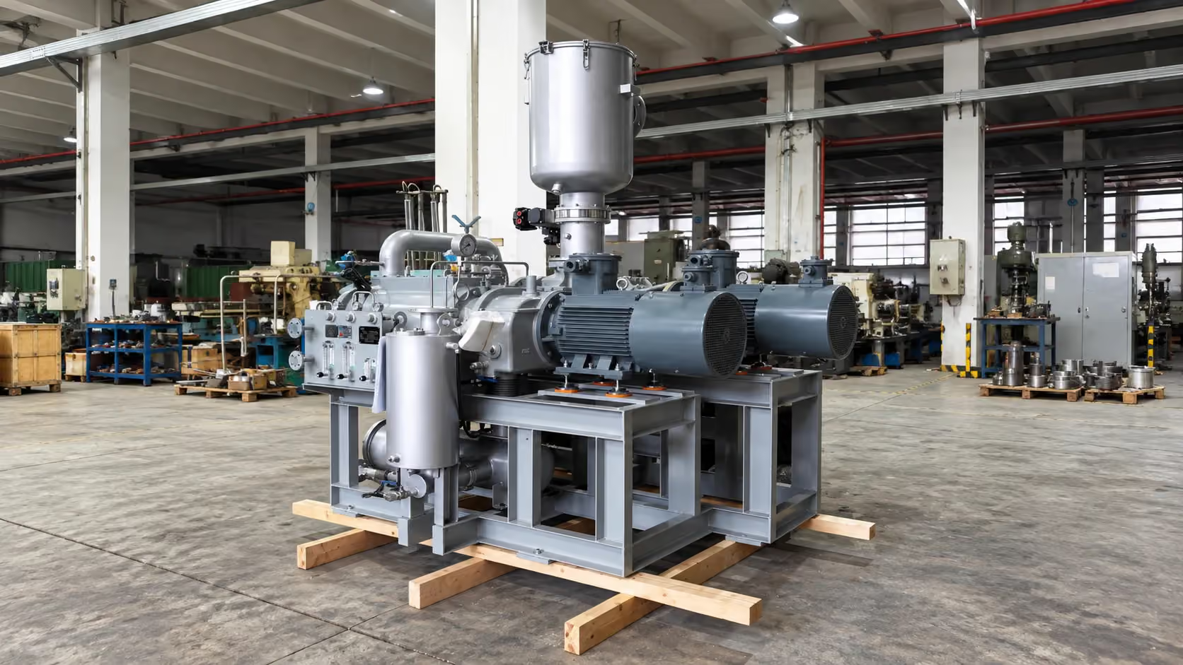
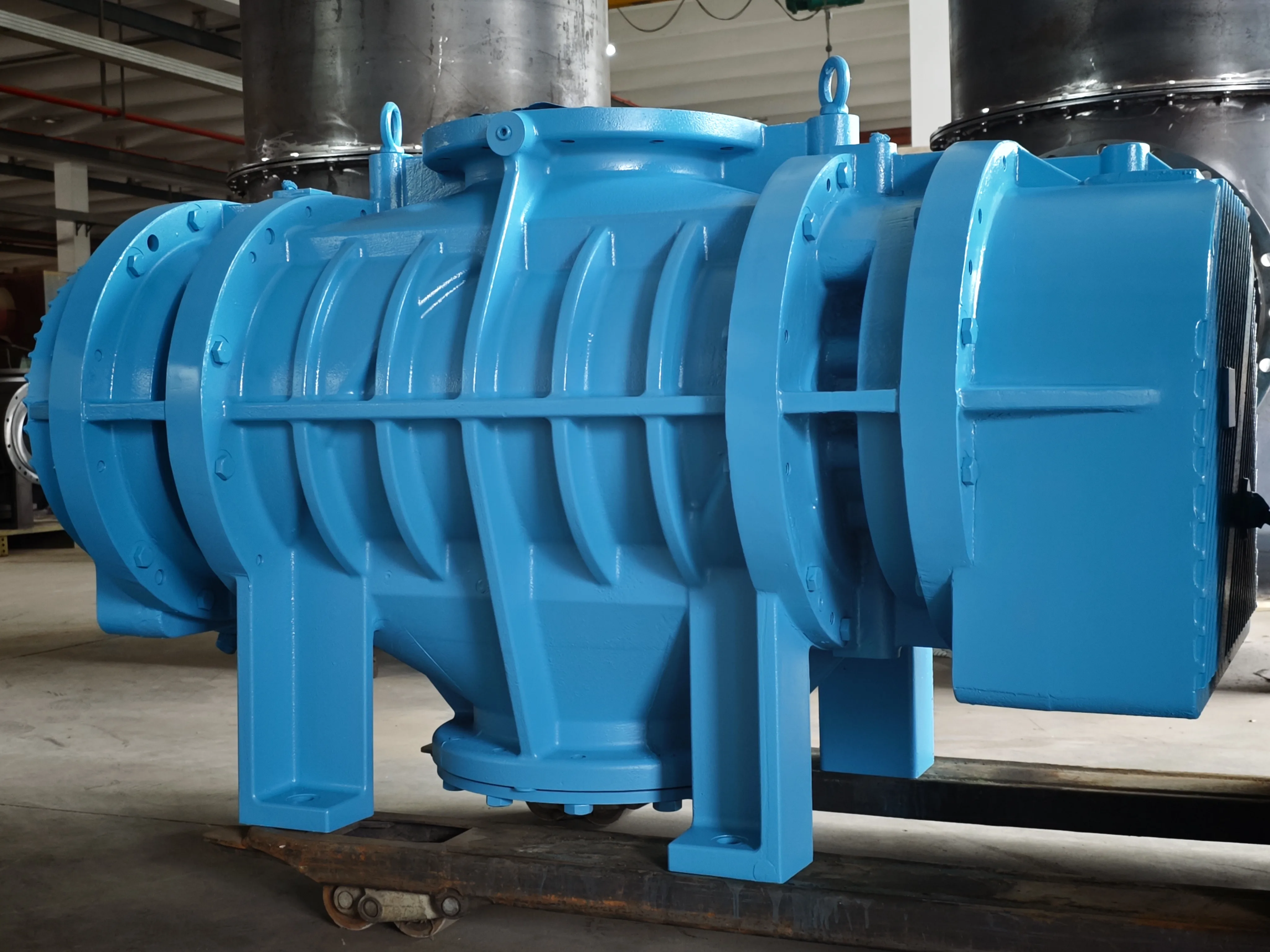
A dry screw vacuum pump utilizes two parallel, non-contacting rotors driven by a pair of synchronous gears to draw gas in at the inlet port, move it through the pumping chamber, progressively compress it as it travels from the suction to the discharge, and release it through the discharging port.
Dry refers to the pumping chamber: it operates without sealing liquid. It does not, by itself, define suitability for a particular gas or vapor stream, liquid carryover condition, dust load, or operating duty. The gas path explains how the pump works, but pump design, working pressure, required volumetric flow rate, gas or vapor condition, dust, liquid carryover, temperature, and duty cycle still shape the configuration review. To begin that review, send us the working pressure and required volumetric flow rate; we can confirm the remaining process and site conditions with you. In this blog, we will discuss what these points mean for the working principle and the first selection review.
What Happens Inside a Dry Screw Vacuum Pump From Inlet to Exhaust?
Inside the pump, the synchronized rotors create a series of working volumes. Each volume takes gas from the suction, carries it toward the discharge, and progressively compresses it as the available space changes along the way. The specific rotor profile, stage arrangement, clearances, and performance curve are confirmed for the selected model.
| Gas-path stage | General principle | What still needs model confirmation |
|---|---|---|
| Inlet | The connected system supplies gas to a working volume near the suction side. | Inlet arrangement, piping, gas load, and the actual operating point. |
| Transport | Rotor movement carries separated gas volumes through the pumping chamber as their available volume changes. | Rotor profile, stage arrangement, clearances, and applicable gas condition. |
| Compression and exhaust | The changing volume progressively compresses gas during transport; gas is released at discharge. | Performance curve, discharge condition, treatment, and site requirements. |
Inlet gas capture
Rotor movement opens a working volume near the inlet. The lower pressure there draws gas from the connected vessel, process line, or system. As the rotors continue to rotate, that volume separates from the suction port.
The rotors and housing form a series of temporary gas volumes, rather than one chamber that remains open from inlet to exhaust. After a volume admits gas, it is carried toward the discharge as the rotors rotate.
The pump is only one part of the inlet system. Pipe diameter and length, valves, filters, separators, leakage, process gas load, and cycle pattern all affect the pressure at the equipment. For that reason, we review the installed duty instead of relying only on an ultimate-pressure label or an old pump nameplate.
This is more than an installation detail: NIST explains that connection diameter, bend count, and pipe length affect the pumping speed available to a vacuum chamber through conductance.1 The final inlet arrangement must therefore be reviewed with the actual duty.
Rotor synchronization
Synchronizing gears keep the two rotors in their relative positions as they rotate. In this dry screw arrangement, the rotors remain non-contacting, so the pumping action does not rely on metal-to-metal contact. When the selected model, installation, and maintenance plan suit the duty, this arrangement supports stable long-term operation.
The changing chamber volume created as the rotors rotate moves the gas through the pump. No sealing liquid is used in the pumping chamber. Rotor profile, coatings, materials, clearances, bearings, gear arrangement, and service requirements vary by model and duty.
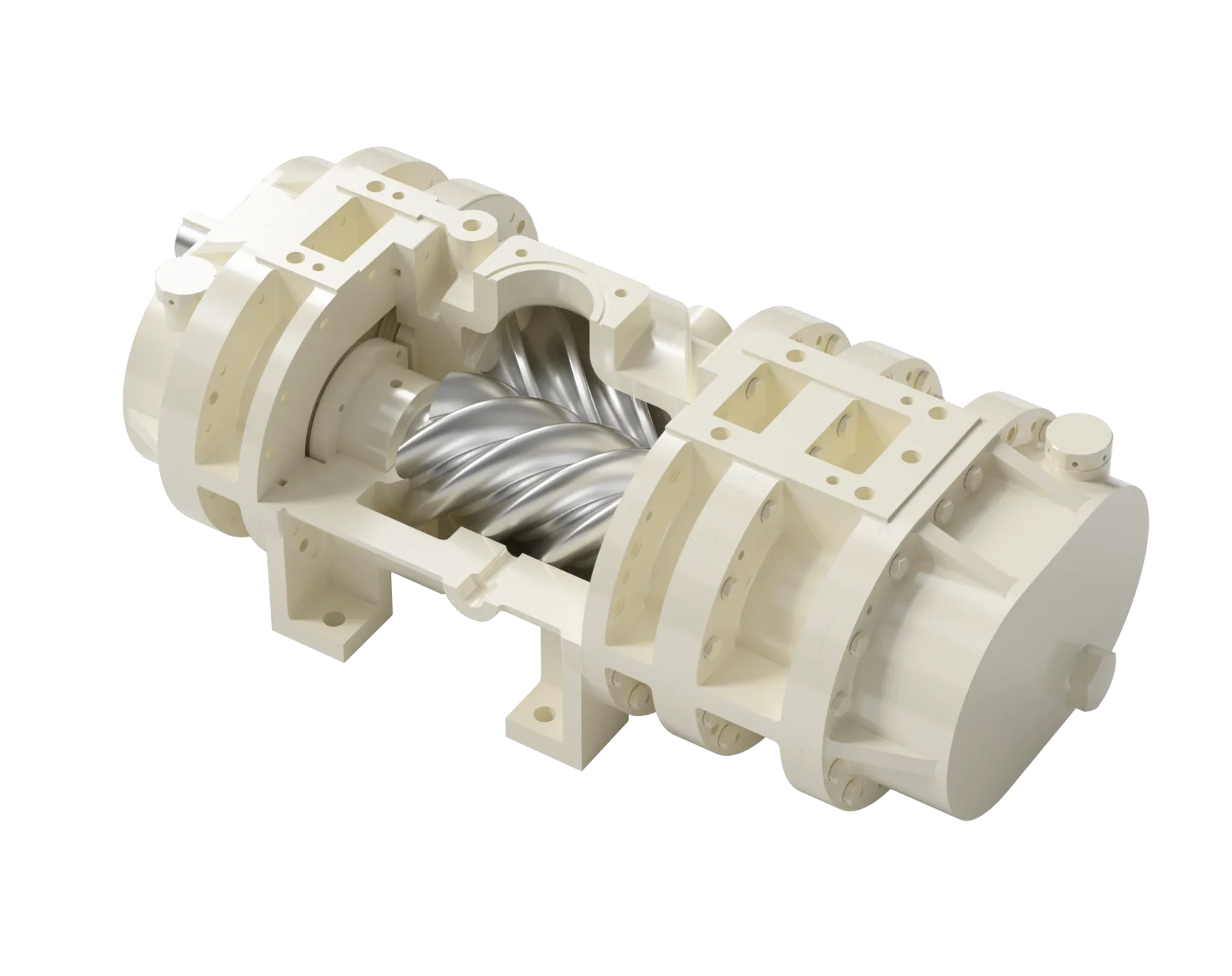
We clarify this early because “two screws” describes only the basic layout. A dry screw pump for rough vacuum and one selected for lower-pressure duty may both use two rotors, but their screw design and configuration can differ.
Gas transport through the chamber
After capture, the rotating rotors carry gas through the pumping chamber from the suction to the discharge. As it moves along the chamber, the changing working volumes progressively compress the gas.
We review the gas condition together with the gas path. Condensable vapor, solids-laden gas, intermittent liquid carryover, and corrosive gas create different requirements from a clean, dry, stable stream. To support stable operation, the pump design may include a pressurized-gas purge arrangement or adjusted rotor and pumping-chamber dimensions to maintain the required clearances.

Beyond the pumping chamber, we also check the complete pump package and connected system. We consider inlet separation, filtration, drainage, cooling, purge arrangements, piping, material selection, seals, and other protective measures around the pump. Here, dry refers to the pumping-chamber principle; the process stream guides the protection and package configuration.
Compression and discharge
Gas is progressively compressed as it travels through the chamber from the suction to the discharge, where it is released. The rotor-profile design determines how the working volumes change along that path.
For an academic explanation of the underlying screw-rotor cycle, Texas A&M research describes successive suction, compression, and discharge phases as the rotor chamber volume changes.2 This reference explains the general rotor principle; it does not define an SC model's profile, stage arrangement, or performance curve.
Roots and dry screw pumps both use rotating elements and can compress gas, so their external layouts can appear similar. The practical distinction lies in the rotor profile: a Roots pump uses a Roots profile, while a dry screw pump may use a Quimby profile or compressor-style symmetric or asymmetric profiles. Before we recommend a configuration, we confirm the working pressure, required volumetric flow rate, gas load, discharge condition, process cycle, and connected equipment.
Discharge conditions are part of the system review. We check the discharge route, expected backpressure, treatment requirements, local site rules, and exhaust-gas composition. This review establishes whether direct discharge can be considered for the stream and site.
Why Does a Dry Screw Vacuum Pump Operate Without Sealing Liquid in the Pumping Chamber?
A dry screw vacuum pump does not use sealing liquid in the pumping chamber. Synchronized rotor geometry and controlled clearances create the working volumes that move gas from the suction to the discharge, with progressive compression along the way. Dry refers to that chamber-level principle; vapor, moisture, droplets, or solids in the inlet stream still need review.
This distinction is useful when comparing a dry screw pump with a liquid ring vacuum pump. In a liquid ring design, the liquid ring contributes to the pumping mechanism. In a dry screw pump, rotor and housing geometry form the gas path. We then review the process duty and inlet stream to define the required configuration.
What dry means in practice
In practical terms, dry means that the pumping chamber creates the pumping action without added sealing liquid. This matters when a buyer wants to keep service liquid out of that chamber. We assess the inlet stream separately to establish material selection and protection requirements.
Vapor can still enter the pump. Gas condition and temperature determine whether it remains gaseous, condenses elsewhere in the system, or calls for a different configuration. Droplets and solids at the inlet require the same review.
We keep the pumping principle separate from the application review. The principle explains the gas path; the application review checks what the gas contains, how it changes through the cycle, and which protection or system measures fit the duty.
Cooling arrangements
SC dry screw vacuum pumps can be reviewed with air-cooled or water-cooled arrangements. Where water cooling is required, a water jacket can be added around the housing. The confirmed model, process duty, available utilities, and site conditions determine the appropriate arrangement.
We assess cooling as part of the thermal and process review. We check gas or vapor condition, inlet temperature, expected ambient conditions, operating schedule, and available utilities. Continuous operation and a short cyclic duty can require different cooling discussions at a similar working pressure.
Inlet protection
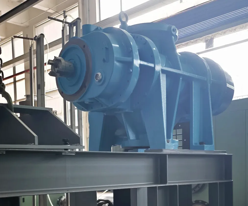
Dry screw vacuum pumps depend on accurately machined clearances to operate normally. Inlet protection helps support stable long-term operation when dust, debris, droplets, or condensable material may reach the pump.
We therefore review what the inlet stream carries and how it behaves before it reaches the pump. Depending on the duty, inlet separation, filtration, drainage, or other package-level protection may be needed to keep material that could disrupt normal operation away from the pumping chamber.
Which Process Conditions Can Change the Working-Principle Discussion?
Process conditions can change the pump model and system configuration even when the rotor principle remains the same. We start with working pressure and required volumetric flow rate, then review gas composition, vapor, liquid carryover, dust, temperature, duty cycle, discharge conditions, and site requirements.
At the same rotational speed, a pump can deliver a different volumetric flow rate at a different working pressure. Capacity data is meaningful only at its stated operating point, so we review working pressure and required volumetric flow rate together before moving to the remaining process conditions.
Working pressure and required volumetric flow rate
Working pressure identifies the process operating point, while required volumetric flow rate states the volume of gas that must be handled at that operating point. For a first inquiry, these two values are enough to begin our review.
We then confirm the remaining process conditions. At the same rotational speed, a pump can deliver a different volumetric flow rate at a different working pressure, so each capacity figure must be read with its stated operating point. The actual value also depends on the confirmed model, gas condition, and measurement basis.
Measurement basis matters as well: NIST notes that gas-flow terminology and units can omit critical temperature information unless the reference conditions are stated.3 Include the units and known measurement basis whenever you send a capacity figure.
An existing pump model or capacity figure is useful supporting information, but it is not needed to start the first discussion. It helps us establish an approximate performance range and understand the existing system as we review the actual duty.
Gas, vapor, liquid carryover, and dust
The inlet stream introduces questions that a working-principle diagram cannot answer. In our review, we establish whether the gas is dry or humid, whether vapor may condense, whether droplets or solids may enter, whether corrosion is a concern, and how the stream changes between startup and normal operation.
These conditions guide the discussion around inlet separation, filtration, drainage, material selection, sealing, cooling, purge, and exhaust handling. For the first RFQ, send the working pressure and required volumetric flow rate first. We can confirm the remaining process questions during follow-up.
Temperature, duty cycle, and site conditions
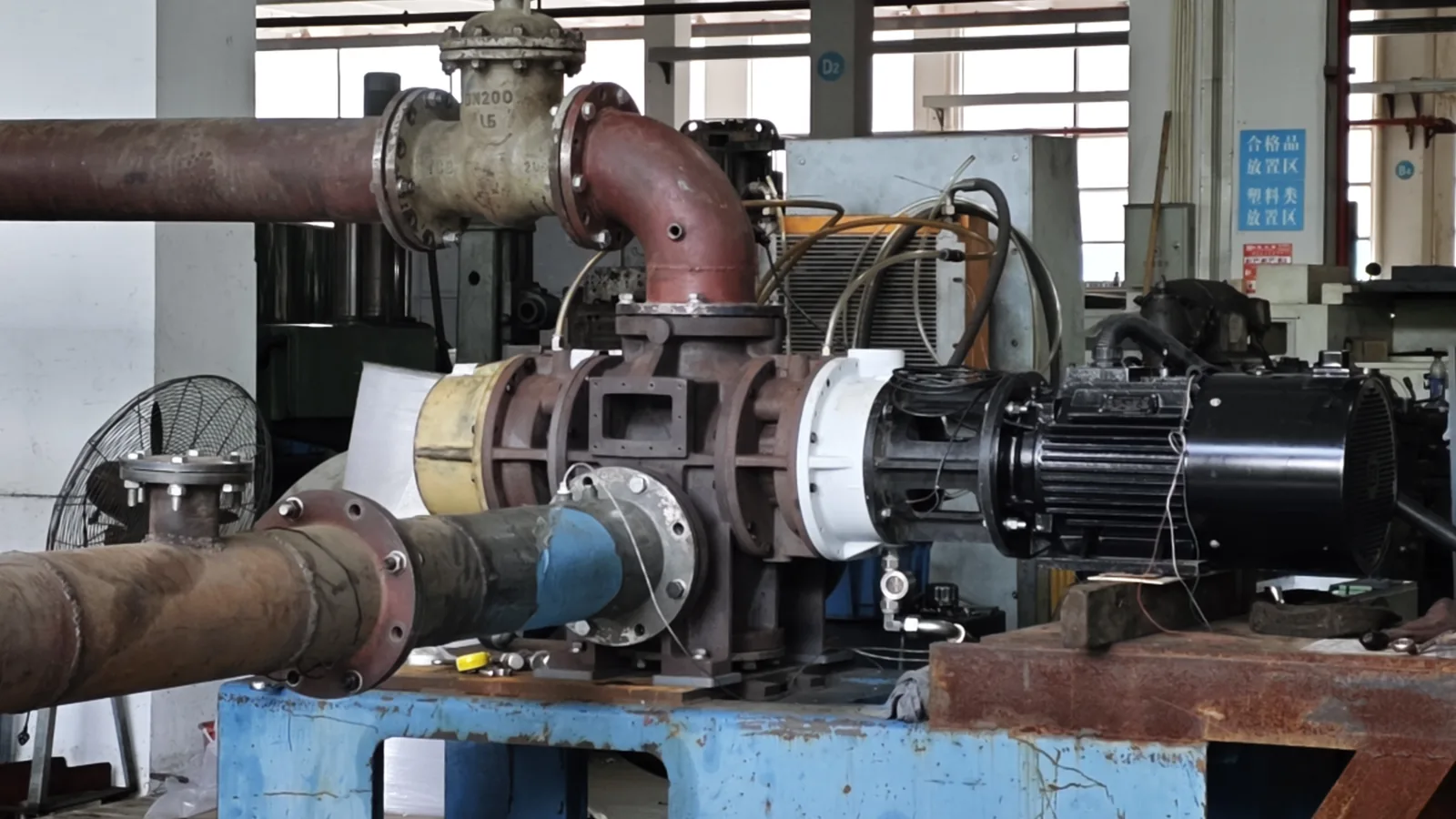
We review temperature conditions together with the cooling arrangement. This includes inlet gas temperature, ambient conditions, cooling-water availability where applicable, and changes during operation. Continuous running, frequent starts, and varying process load can each lead to different cooling and configuration questions.
Once the operating point is known, we also confirm site constraints: electrical configuration, ventilation, maintenance access, piping layout, installation location, discharge route, and safety requirements.
Review inputs at a glance
| What we review | Why it matters | When to provide it |
|---|---|---|
| Working pressure | It sets the operating point for the capacity review. | First inquiry: the expected working pressure, with units and absolute/gauge basis if known. |
| Required volumetric flow rate | It states the volume of gas the pump must handle at that operating point. | First inquiry: the required volumetric flow rate and its units. |
| Gas or vapor condition | It guides the review of condensation, corrosion, treatment, and materials. | Follow-up: a simple process-gas description and any known vapor. |
| Liquid carryover and dust | It guides inlet protection, separation, drainage, and filtration. | Follow-up: whether droplets, solids, or debris may reach the pump inlet. |
| Temperature and duty cycle | They guide cooling and operating-pattern questions. | Follow-up: known inlet and ambient temperatures, plus continuous or cyclic operation. |
| Discharge and site constraints | They guide the pump package and connected-system configuration. | Follow-up: the discharge arrangement, available utilities, and notable site restrictions. |
What Should You Send Us After Understanding the Working Principle?
To begin the review, send us the working pressure and required volumetric flow rate. These two values establish the operating point; we then confirm the process stream and site conditions needed for the model and configuration.
This keeps the first conversation straightforward. An existing pump model, a working-principle question, or a current liquid-ring setup can be useful context, while we confirm the remaining process details during follow-up.
First RFQ information
For a first RFQ, start with the two operating-point values below. The process description and existing pump model are helpful if available, but they are not needed to begin.
- Working pressure, with units and absolute or gauge basis if known.
- Required volumetric flow rate at that working pressure, with units.
- Optional: the process or equipment using the vacuum.
- Optional: an existing pump model, if one is installed, as a reference.
During follow-up, we confirm gas or vapor condition, inlet temperature, liquid carryover, dust, operating schedule, cooling, exhaust routing, and site requirements. These conditions guide the pump or system configuration.
Existing pump reference
An installed liquid ring pump, Roots pump, or other vacuum pump gives us useful background for the first review. Its model and installation can show the current connection size, operating pattern, known process issues, or an approximate performance range.
Before discussing a replacement, we compare the existing installation with the working pressure and required volumetric flow rate. When reliable data are unavailable, pressure readings, process timing, piping information, and a clear inlet-stream description help us build a clearer picture of the duty.
From principle to selection
The working principle explains how a dry screw pump moves and progressively compresses gas from the suction to the discharge without sealing liquid in the pumping chamber. The selection review starts with the operating point, then confirms inlet conditions, the process stream, and the discharge boundary.
See our dry screw vacuum pump page for a product overview. For the operating-point logic, read How to choose a dry screw vacuum pump by working pressure and required volumetric flow rate. To begin a review, send the information you have through our contact page.
What Are the Frequently Asked Questions About Dry Screw Vacuum Pump Working Principle?
These questions separate the general pumping principle from the model- and process-specific review needed for an industrial duty.
How does a dry screw vacuum pump create vacuum?
A dry screw vacuum pump creates vacuum by removing gas from the connected system. Its synchronized, non-contacting rotors form working volumes that take gas in at the inlet, carry it through the pumping chamber, progressively compress it from the suction to the discharge, and release it through the discharge port.
Process pressure falls when the pump removes gas faster than the system admits it through process load, leakage, or intentional gas introduction. The actual operating condition also depends on the pump, piping, gas load, and system arrangement.
Does dry mean a dry screw vacuum pump can handle every gas or liquid condition?
No. “Dry” means the pumping chamber creates the pumping action without sealing liquid. The inlet stream still guides the review of corrosive vapor, condensation, liquid carryover, dust, and process-specific protection.
Once the initial operating point is known, we review those conditions with you. Depending on the duty, this may include inlet protection, separation, drainage, materials, seals, cooling, purge arrangements, and discharge treatment.
Is a dry screw vacuum pump the same as a Roots pump?
No. Both use rotating elements and have compression capability, but their rotor-profile designs differ. A Roots pump uses a Roots profile, while a dry screw pump may use a Quimby profile or compressor-style symmetric or asymmetric profiles.
The right technology or system arrangement follows the actual process requirement. We review the operating duty rather than selecting from rotor appearance or a broad category name.
References
- 1. "Vacuum Technology Considerations for Mass Metrology", National Institute of Standards and Technology. https://nvlpubs.nist.gov/nistpubs/jres/116/4/V116.N04.A01.pdf. Evidence role: vacuum-system context. Supports: connection diameter, bends, and piping length affect available pumping speed through conductance. Scope note: this supports the general inlet-system principle, not an SC model-specific performance value.↩
- 2. "Dry Screw Compressor Performance and Application Range", Texas A&M University. https://oaktrust.library.tamu.edu/server/api/core/bitstreams/155b280f-60ff-4054-ab1a-a45ba859ff5b/content. Evidence role: general screw-rotor mechanism. Supports: successive suction, compression, and discharge phases as a working chamber changes volume. Scope note: this supports the general mechanism only; it does not establish SC rotor profiles, stages, or performance.↩
- 3. "A Note on Flow Rate and Leak Rate Units", National Institute of Standards and Technology. https://www.nist.gov/publications/note-flow-rate-and-leak-rate-units. Evidence role: measurement basis. Supports: gas-flow terminology and units can omit critical temperature information if reference conditions are not stated. Scope note: this explains why capacity data need units and a known measurement basis; it does not define a pump's performance curve.↩